The basic idea is that we can run many (but not all) of the Space Nerds in Space bridge stations on a Raspberry Pi, and have an arduino connected to the Pi, and connected to the arduino can be a load of potentiometers and switches and LEDs. These potentiometers and switches can be logically connnected to buttons and sliders within the game. The arduino can poll the state of the switches and potentiometers and report changes to the game via the USB serial back to a process on the the raspberry pi which can then feed these changes into the game via the interface provided by snis-device-io.h. Likewise, LEDS for warning lights, etc. can be controlled from the game via USB serial to to the arduino. In this way we can build a physical console for each of the stations to make the game seem a little more like a spaceship and little less like a computer game.
Why Arduino? Because arduino is accessible and open source. It's possible other people besides me may want to build something like this, and Arduino is the easiest, most well-known and popular thing in its class, and most likely to be something that other people will be able to work with.
I got my homemade flight yoke working. Here's a video of it.
To use all this:
This is all just test code at this point. I plan to integrate this yoke into a larger simulator control panel. I will probably move to using a Raspberry Pi pico rather than an Arduino because it just makes more sense price/feature-wise.
Received 200x 4p4c plugs and crimping tool.
Well, it turns out that the connector on the cable from the rudder pedals is not an RJ12 6p6c connector. It's some other kind of 6p6c connector that looks sort of like RJ12 but isn't. Digging around, it appears to be a "RJ12 DEC 6p6c modular plug with left latch offset tab". You can find these plugs on amazon ($0.50 each) but the jacks may be unobtainium. Might have to add a second cable to my rudder pedals with a more common connector.
Received some parts today:
When I first began thinking about this project of building physical controls for SNIS back in 2014 or so, and even up to 2020, the Arduino seemed a sensible choice, especially if a goal is to make the project somewhat approachable for other people to build their own version, due to the Arduino's popularity and mindshare. And it would still work today, but I can't help but look over at the Raspberry Pi pico. With its sub $5 price point, (relatively) large memory and (relatively) high performance 32-bit CPU, and its considerable popularity, it seems a little silly to be using an Arduino in 2023 with its ancient, slow, awkward 8-bit CPU and kind of weird development environment (although I understand that dev environment is part of the attraction for a lot of people.) Anyway... I am seriously thinking of switching to the Raspberry Pi pico for this project.
I came across this ghetto-genius idea for building a yoke using a mouse as the sensor for both pitch and roll: https://wiki.flightgear.org/Howto:Build_a_yoke_in_5_minutes. And this page about how to interface an Arduino with a mouse sensor: https://www.instructables.com/Interfacing-With-a-Mouse-Sensor-ADNS-3050/.
Received 200ft 4 conductor flat modular phone wire, a bunch of female headers, and a bunch of male-to-male DuPont wires. Still awaiting 200x 4p4c RJ11 plugs and jacks, and the crimping tool for the plugs (from aliexpress, so it'll be awhile.)
Previously I mentioned that USB game controllers seemed to assume only one RGB LED, judging by SDL2's API:
int SDL_GameControllerSetLED(SDL_GameController *gamecontroller, Uint8 red, Uint8 green, Uint8 blue);
However, it now occurs to me that this API could be used to individually control (turn on/off) up to 24 LEDs, and that is probably enough.
On second thought, an entire made-up protocol could be transmitted through this API, for example, maybe using the R byte as an opcode, and the G and B bytes as operands, and in this way any arbitrary data may be sent to the device.
I am assuming a bit about what happens when SDL_GameControllerSetLED() is called, namely I assume that it transmits some sort of command to the device with each call, rather than say, merely setting a register or variable in the driver that gets periodically polled or sent to the device on a time schedule, in which case the sequence of commands might not be preserved if multiple commands are sent in a single polling cycle.
However... looking at https://github.com/libsdl-org/SDL/blob/main/src/joystick/linux/SDL_sysjoystick.c#L1544...
static int LINUX_JoystickSetLED(SDL_Joystick *joystick, Uint8 red, Uint8 green, Uint8 blue)
{
    return SDL_Unsupported();
}
... sad trombone noises ...
OTOH, for joystick support, SNIS does not actually use SDL2, it uses read(2) to read from the joystick device file directly, so all hope is not lost.
Went ahead and ordered 200x 4p4c female RJ11 jacks with wires, 200x 4p4c male RJ11 plugs, 200ft of 4 conductor modular phone cord, and a tool to crimp the plugs onto the phone cord. With shipping, total came to around $90.
Experimentally, messing around with 2 LEDs and a few 560 ohm resistors and a power supply. With 2 560 ohm resistors in series with 2 3mm white LEDs, brightness was fine, voltage across each LED was about 3V (fine), current was about 4mA (fine).
I have been thinking about the wiring and connectors between the buttons and the circuit board brain of this contraption. Been playing around with crimping DuPont connectors, and, well, turns out that I hate DuPont connectors. Crimping them sucks, (I don't have quite the right tool), but even with perfect crimping, after that, you're left with a DuPont connector, which inherently sucks anyway.
Then I started thinking of crazy ideas, like:
I played around with that idea for a few minutes, but found the practical matter of soldering the wires, even with the DuPont connector pins holding things together, was just not working. Could not make a strong connection reliably. Plus crimping DuPont connectors just sucks. Didn't get as far as sealing the mess inside plastic with the 3Doodler before declaring this whole idea of making my own damn connectors to be insane, and abandoning it.
A friend suggested RJ11 4p4c jacks, plugs, and phone wire. This would be neat, because my buttons have 4 wires, 2 for the LEDs, and 2 for the button. Digging around on amazon, at first this seemed to be too expensive. But then digging around on aliexpress, the female jacks with wires are about $0.07 each, the male plugs are $0.0375 each, and 4 conductor phone cord is about $0.10 per foot. And a crimping tool for the plugs is around $8. That is affordable. I could make a little 3D printed housing to mount the female jacks into, and use the 3Doodler to weld those to the back of my buttons. So far, this phone cord idea for wiring seems pretty good.
What if the whole thing shows up as a USB game controller? I already have support in snis_client for customizable game controller setups, so if possible, that seems like a win.
I do have some concerns though. Game controllers have "buttons" and "axes". The send "button up" and "button down" events to the host, and axis movement events (e.g. digitized potentiometer voltage readings). However, a toggle switch isn't so easily modelled. Maybe a "button down + button up" event for "on", and a "button up" event for off could work? And what about controlling LEDs? Not sure how that is done. If these can be solved, then a USB game controller would require much less work on the software end of things, I think. Also, I was thinking about making some dial gauges with servos or stepper motors, and those would need to be controlled somehow. I don't think game controllers have any such capabilities.
Hmm, SDL2 has:
int SDL_GameControllerSetLED(SDL_GameController *gamecontroller, Uint8 red, Uint8 green, Uint8 blue);

gamecontroller    The controller to update
           red    The intensity of the red LED
         green    The intensity of the green LED
          blue    The intensity of the blue LED
So... gamecontrollers only have one LED, and it's an RGB LED and all you can do is set the color? That's not really going to work.
Some GPL'ed software for ATMega here: https://www.raphnet.net/electronique/usb_game12/index_en.php#2
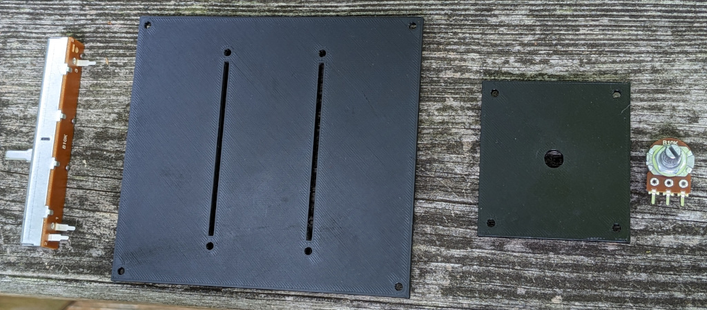
One of the things which has been holding up this SNIS Consoles projects is that I didn't have a good idea about how to physically build the control panel surface that I found entirely satisfactory.
The "professional" way to do it is to get some sheet steel or aluminum and cut and drill holes of the right sizes and shapes, deburr, powder coat, and screw all the components (potentiometers, switches, faders, etc.) into the panel. That gets expensive real quick. If you're Mr. Behringer, and you have a load of factories in China, that's no problem, but I'm just a guy, I don't even have a garage. A cheaper and easier way that is common among hobbyists is to laser cut acrylic sheets and use that instead of steel or aluminum. But for me, there are a few of problems with this. First, it has a certain look. Perfect if you're going for a Star Trek LCARS styel panel, but that's not what I'm going for. I'm going for something a little more "Apollo capsule", or "fighter jet cockpit". Second, if the panel is thin enough to mount inexpensive potentiometers and it is large, it might flex too much. This can be mitigated by gluing beams of reinforcement webbing on the underside of the panel though. Finally, while acrylic initially looks great (if that's the look you're going for) it has a tendency to get scratched up over time, especially for something that is hands-on, like a control panel.
But now I think I have come up with a method that should be inexpensive, durable, easy, good looking (with some paint), and did I mention inexpensive?
Here's the idea: Make the panel out of thin plywood. Cut out large rectangular holes for panel inserts. Mount the hardware (pots, switches, faders, etc) to the panel inserts with a laser cutter. Finally, make the panel inserts by 3D printing them. That's right, 3D printing. Doing it this way, the panel and inserts are practically free (assuming you have access to a 3D printer and a laser cutter, which if you're in a reasonably large city with a makerspace, you probably do have such access.)
Here are a couple prototype panel inserts I printed yesterday, one to hold a couple 60mm faders and one to hold a potentiometer. They feel pretty sturdy.
Prototype panel insert, front
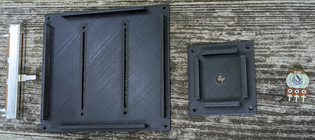
Prototype panel insert, back
No dimensions on a 3D print survive first plastic, and these are no exceptions. The hole for the potentiometer is slightly too small, and the face plate is a little too thick, and the screw holes for the faders don't match up quite right, but you get the idea, and with tweaking it can be made to work.
Speaking of the screws, I have another idea for the 2nd iteration. I was looking at the 60mm fader, and I noticed that it has a little circuit board on the bottom, and the circuit board is held tightly to the metal casing by little metal tabs that are part of the casing, and folded over to hug the circuit board. Hmm. It occurs to me that I may not need all these screws, which it turns out can be surprisingly expensive to source. I can integrate some plastic clips and ridges into the back side of the panel insert to allow the faders to just be snapped into place. Likewise, I can add some clips around the edges of the panel inserts so they can just snap into the plywood control panel.
Came across this video of an interesting gauge:
It uses an X27-589 stepper motor (same as X27-168 but with pins on the front side). Recommended stepper driver: Vid6606 (STI6606) 4x Stepper Driver for X27.168
This solution appears to be quite expensive (for me), about $20 for the stepper motor and $24 for the stepper motor driver. With manufactured PCBs, maybe it's around $40-$50 per gauge.
More ideas from this other video, some gauges using cheap servo motors: https://www.youtube.com/watch?v=Ib9axlfK0f4 (9g servo motors can be had for around $2 apiece, which is more my speed.)
Implemented an idea by Shadow8472, which is to allow running snis_client with no textures (actually with 1 bogus textures). Many of the stations (Navigation, Engineering Damage Control, Science, and COMMs) do not use any textures. For phyiscal consoles which are meant to be used with a single station, it doesn't make sense to load all these textures only to not use any of them. So I added a "--no-textures" option to snis_client and an item in the "Options" menu of snis_launcher to enable it. Briefly observing the resident memory usage of snis_client with htop showed it using about 700M with textures and about 300M without, saving 400M, over half the memory used.
Tested out my amplifiers and speakers:
Got pico2wave working on Raspberry pi.
Needed to:
	wget -q https://ftp-master.debian.org/keys/release-10.asc -O- | sudo apt-key add -
	echo "deb http://deb.debian.org/debian buster non-free" | sudo tee -a /etc/apt/sources.list
	sudo apt-get update
	sudo apt-get install libttspico-utils
Also needed to install pulseaudio and sox (sox for "play" command).
	sudo apt-get install pulseaudio
	sudo apt-get install sox
I think that's it... might have been some more steps though. Will have to try with additional Raspbery Pi's and update these instructions if necessary.
Received 5 pairs of speakers.
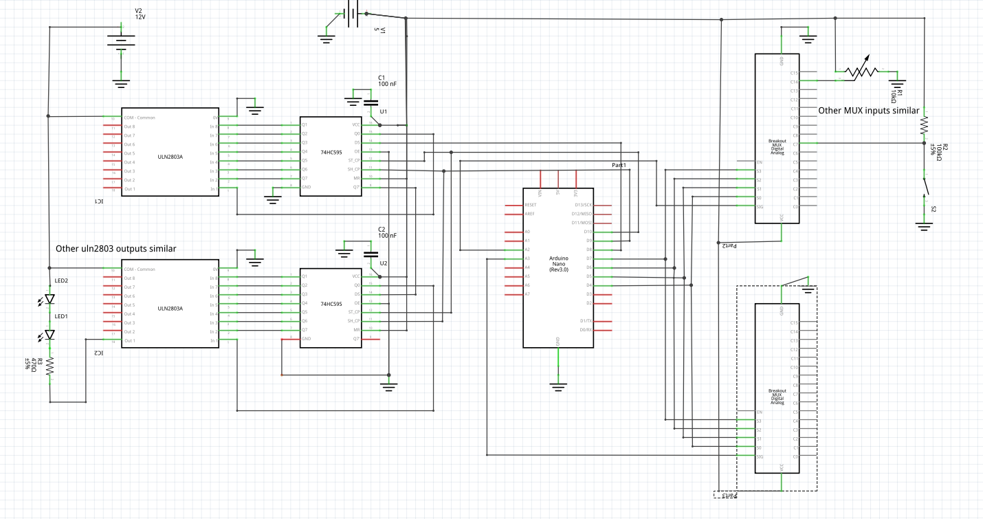
Added some test code to snis_console program, and fixed some bugs in the code. Now I think it should be working right. Still need to add code to snis client to send LED data to snis_arduino, and modify snis_arduino to forward this data to the arduino.
Received 5x 20W/ch class D stereo amplifiers based on YDA136-E. Haven't tried them yet. Still awaiting speakers.
Received 200 each of 560 and 470 ohm resistors. I think that's the last of the parts I need to begin assembling a board.
Ordered 5 YDA138 based 20W/ch amplifiers and 5 pairs of 5W speakers from Aliexpress (total was $50.xx).
Received shipment of 3 24-inch monitors, 4 HDMI cables, and 5 Arduino Nano clones (but only one USB cable for the Arduinos, so I'll need some more USB cables.)
Received shipment of 200 white LEDs, 120 tactile switches, 5 12V power supplies, and 4 power strips,
Some notes about the shift register:
       ---U---
   Qb -       - Vcc
   Qc -       - Qa
   Qd -       - SER   (DS)
   Qe -       - OE    (DE)
   Qf -       - RCLK  (ST_CP)
   Qg -       - SRCLK (SH_CP)
   Qh -       - SRCLR (MR)
  GND -       - Vcc
       -------

  Qa-Qh are outputs.
  OE is Output Enable.  It must be 0v to enable outputs. (tie to ground).
  SRCLR is Shift Register Clear, which clears the shift register
        when low.
  SER is the serial data input.
  SRCLK is the storage register clock
  RCLK is the register clock. I think this is a latch which makes this inputs appear
       on the outputs.  I *think* you can clock in 8 bits via SER and rising edge of
       SRCLK, then clock RCLK (rising edge) to have the outputs change all at once.
  SRCLR clears the shift register if low. I think I can just tie this to high.
Here is a circuit diagram (no guarantees of correctness):
Got my aviation style 3d printed switch case thing working pretty well. Put it on Thingiverse.
The LEDs I'm using have a forward voltage of 3.0 to 3.2V. Current should be 15-18mA, and the power supply will be 12V DC. So for resistor, I need:
        R = (Vs - Vf) / If
          >= (12 - 3.2) / 0.018
          <= (12 - 3.0) / 0.015
          = 488.8-600 Ohm

    power = (12 - 3.0) *  0.018
          = 0.1628W (so, 1/4th watt resistor).
That's for 1 LED, for 2 LEDs in series:
        R = (Vs - Vf) / If
          >= (12 - 3.2 - 3.2) / 0.018
          <= (12 - 3.0 - 3.0) / 0.015
          = 311-400 Ohm

    power = (12 - 3.0 - 3.0) * 0.018
          = 0.108W (so, 1/4th watt resistor).
So, for single LED, I need some 600 Ohm 1/4W resistors, and for double LEDs in series, 400 Ohm 1/4W resistors.
Testing this out, it might be a little bright, so might need to up the resistor values, or put another resistor in series with all the LEDs to drop the voltage down a bit. Experimenting, 5V with two LEDs just barelly turns them on, 6V turns them on dimly, then the brightness ramps up as you crank the voltage up to 12V. Probably 8 or 9V is about right.
It seems that powering the Arduino via the Raspberry Pi's USB is fine, however, there's not a lot of current available, so I will need to have another 5v power supply for powering LEDs.
For switches, the lighted Apollo mission type switches are called Tellite switches and they are prohibitively expensive. However, I might be able to come up with a reasonable facsimile using some cheap LEDs, laser cut acrylic and laser printed paper labels to fit over some cheap push buttons.
It seems I'm not the only one with approximately this idea:
Here is the pushbuttons design on thingiverse. Looks like he deleted the design files, but maybe something here: https://www.tinkercad.com/things/fQeSDCBttU3-push-buttons. However, I'd want to design my own anyway with OpenSCAD.
Going through the screens, here are the switches and pots needed:
Totals:
Was talking with Rob last night at HackRVA, and we are going to build a vacuum forming machine. This should help with building the cases for the consoles. I have a few ideas about how to paint them. One idea, vacuum form them from clear PETG, then paint the inside with silver paint. Should look like mylar, more or less. Not sure I like that idea. Another idea, put some HVAC tape on select edges, paint with black, dark gray, or hammered metal, then sand off a bit to expose some of the silver HVAC tape. I think I'll probably do the latter method.
I changed the protocol used over the serial USB so that the '#' is replaced by the first letter of the station, so 'E' for engineering, 'C' for comms, 'W' for weapons, 'S' for science, 'D' for demon, 'N' for navigation. Only engineering is implemented yet. I'm using a #define to control which station the code compiles for.
Ordered 20 ULN2803 darlington arrays to drive LEDs from amazon, should be here in 2-4 weeks. Ordered some shift registers and male pin headers from futurlec, who knows when those will arrive. (I noticed there are some male pin heads lying around HackRVA though, so no need to wait for those, ha.)
Looking into building a vacuum forming machine to use for making the console cases.
Made some progress, there's a new program in the space-nerds-in-space repo called snis_arduino that reads from the arduino and passes along commands from the arduino to snis_client. I updated the program which runs on the arduino itself (snis-console.c.ino) so it actually works. The main change I made was to switch to a text protocol from binary. This avoids de-syncing as I can look for a newline to delimit the commands. Now the commands from the arduino to the host (raspberry pi) are of the form: "#xxx=yyy\n", where xxx is the input number (0 - 31) and yyy is the value for that input. The values are only reported to the host if they differ from the previous sampling by more than 3.
Another change I made on the host side (snis_arduino) has to do with the problem I was seeing in which it would read a little bit then quit upon encountering EOF. It turns out that reading from /dev/ttyACM0 is apparently non-blocking, despite not opening it with O_NONBLOCK, which sort of surprises me. So I changed the code to simply wait for a few milliseconds and try again upon encountering EOF, and this seemed to make it work.
Video here: https://www.youtube.com/watch?v=51ljGNx3px4.
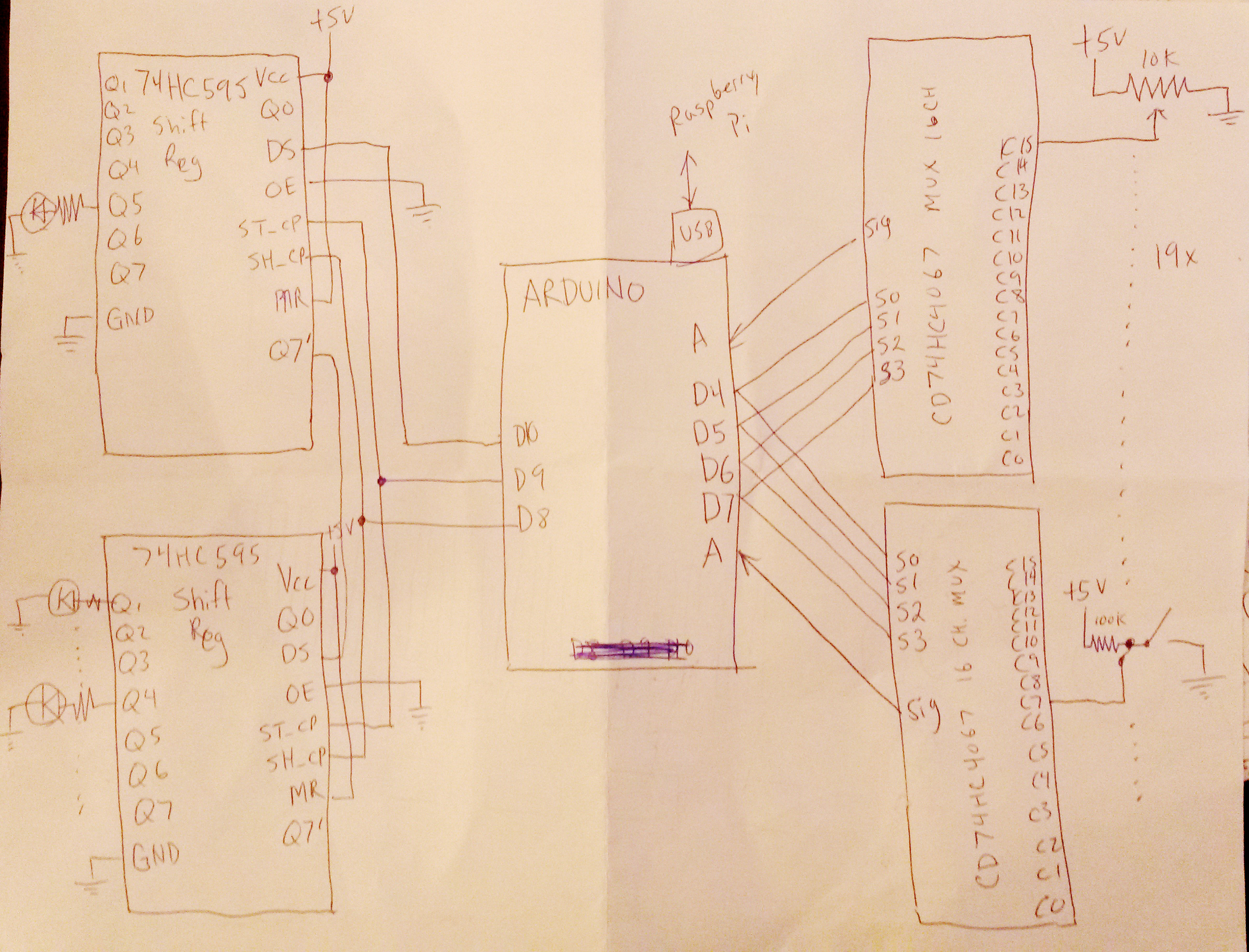
On the output side, two daisy chained shift registers allow up to 16 LEDs to be controlled. Likely I will need to add NPN transistors to drive each of the LEDs to avoid drawing too much current from the shift registers.
Pseudocode for the arduino will be something along these lines:
	static int new_value[32] = { 0 };
	static int old_value[32] = { 0 };
	static int led_status[16] = { 0 };

	setup()
	{
		Set up 4 digital outputs D4 thru D7 for selecting the multiplexer channels.
		Set up 2 analog inputs for the multiplexer signals.
		Set up 3 digital outputs for the shift register controls
		set up interrupt handler for incoming serial data
	}

	select_multiplexer_channel(int n)
	{
		D4 = i & 0x01;
		D5 = (i >> 1) & 0x01;
		D5 = (i >> 2) & 0x01;
		D5 = (i >> 3) & 0x01;
	}

	sample_inputs_from_multiplexer(int new_value[])
	{

		for (int i = 0; i < 16; i++) {
			select_multiplexer_channel(i);
			new_value[i] = read_multiplexer(0);
			new_value[i + 16] = read_multiplexer(1);
		}
	}

	transmit_changes(new_value, old_value)
	{
		for (i = 0; i < 32; i++) {
			if (old_value[i] != new_value[i])
				transmit_value(i, new_value[i]);
		}
	}

	update_led_status()
	{
		/* Shift LED data out to shift register */
		for (i = 0; i < 16; i++) {
			set DS = 0;
			set ST_CP = led_status[i];
			set DS = 1;
		}
		set DS = 0;

		/* Latch LED data (need to double check this is how it works) */
		set SH_CP = 0;
		set SH_CP = 1;
		set SH_CP = 0;
	}

	serial_interrupt_handler()
	{
		/* still need to work out whatever the protocol is for LED data */
		/* Could be just pairs of bytes. */
		get_character_from_serial()
		decode_character();
	}

	loop()
	{
		sample_inputs_from_multiplexer(new_value);
		transmit_changes(new_value, old_value);
		memcpy(old_value, new_value, sizeof(old_value));
		update_led_status();
	}